Acquisition
Cerebral Aqueduct CSF Sequence Parameters
Below are a summary of parameters for phase contrast pulse sequences that have been tested on multiple manufactuerers. Though a particular application may require different parameters, this reference should provide a starting point for developing a functioning phase contrast pulse sequence.
| Parameter | Philips | Siemens 1 | Siemens 2 | GE (TBD) |
|---|---|---|---|---|
| Pulse sequence | Gradient Echo | Gradient Echo | Gradient Echo | |
| ETL | 3 | 1 | 1 | |
| TE | 16.63 | 5.68 | 7.54 | |
| TR | 26.32 | 25.56 | 44.56 | |
| NSA | 6 | 2 | 3 | |
| Voxel size (mm) | 0.45x0.45 | 0.39x0.39 | 0.27x0.27 | |
| Slice | 5 | 5 | 5 | |
| Slice gap | 5 | |||
| Bandwidth | 96 | 399 | 310 | |
| Acceleration | ||||
| Venc | 30 | +/-10 | +/-10 | |
| Venc dir | through | through | through |
The following references include additonal parameters that have been used successfully in a variety of configurations.
- References
Cerebral Aqueduct CSF Flow Placement
Download Example Images
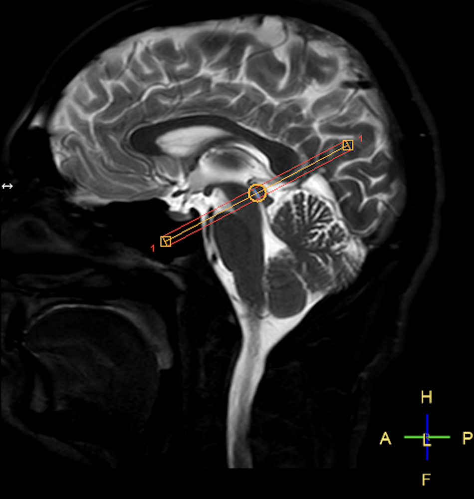
The appropriate placement of an imaging plane for using phase contrast to examine cerebral aqueduct CSF flow is demonstrated below. We recommend starting with a transverse slice and aligning the imaging plane to be orthogonal to the cerebral aqueduct, and place the plane approximately half way between the third and fourth ventricles. The imaged from this orthogonal slice will be used to determine the flow rate through the cerebral aqueduct.
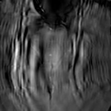
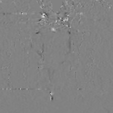
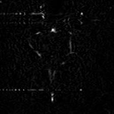
The magnitude and complex difference images are useful for identifying the aqueduct, and the phase image contains the velocity information needed to measure flow.
| Magnitude Image | Phase Image | Complex difference image |
|---|---|---|
 |
 |
 |
Video of PC in the cerebral aqueduct
Shunt CSF Sequence Parameters
- Reference
Shunt Flow Placement
Locating the shunt and lumen can be quite difficult, thus we recommend performing a T2 axial image acquisition before attempting to place the imaging slice for shunt flow. Then. we recommend measuring flow on the distal (after shunt valve) side to avoid pulsatile effects on the proximal side of the valve. We also suggest imaging at least 2 cm away from programmable shunt valves to avoid image artifacts that might otherwise corrupt images.
Cerebral Blood Flow Sequence Parameters
Internal Carotid Artery Flow Placement
| Phase Contrast | Angio Image |
|---|---|
 |
 |
Download Example Images
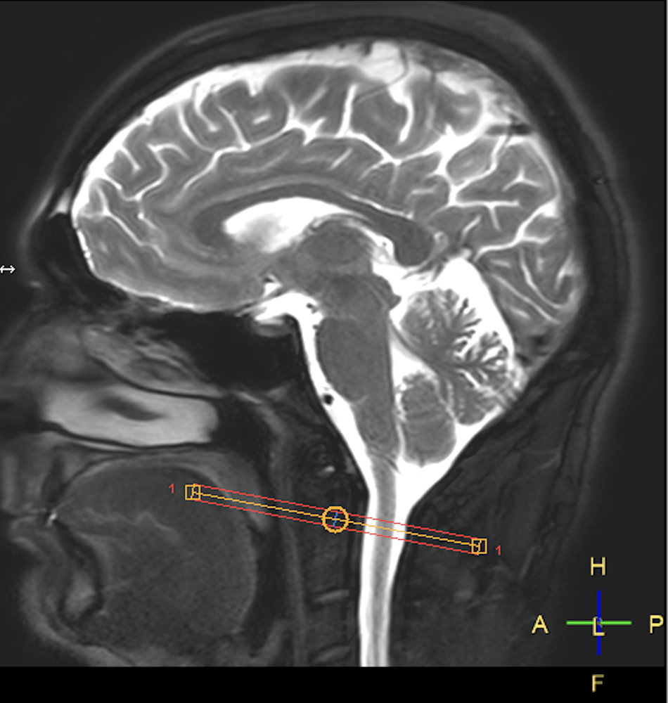
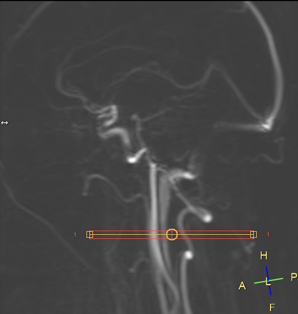
The appropriate placement of an imaging plane for using phase contrast to examine total cerebral blood flow is demonstrated here. We recommend starting with a transverse slice and aligning the imaging plane to be orthogonal to the internal carotid arteries and place the plane approximately at the top of the C2 vertebral body. If time permits, an angiography survey can be should acquired because it can be used to place the phase contrast imaging plane perpendicular to the vessels.
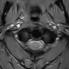
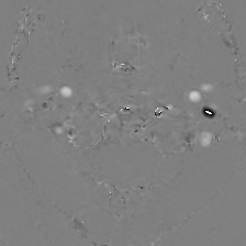
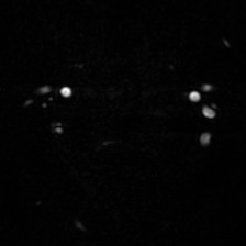
The resulting transverse slices will demonstrate internal carotid vertebral arteries. The complex difference image is useful for determining where the vessels are, and the phase image will ultimately be used to determine the flow rate through the arteries at this location.
| Magnitude | Phase | Complex Difference |
|---|---|---|
 |
 |
 |
If time allows, best practices include separate measurements of all four vessels (2 internal carotid arteries and 2 vertebral arteries). Alternatively, when time is critical we recommend a single slice through the two internal carotid arteries. These vessels tend to be quite parallel, carry approximately 70% of the overall flow to the brain, and measuring only these vessels is well correlated (r-squared>0.99) with total cerebral blood flow.
If any vessels are missed, their values can be imputed using this calculator.